Vishnu Aishwaryan Subra Mani

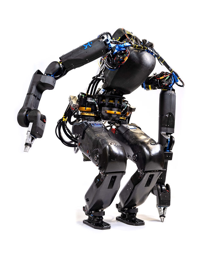
IHMC is developing a next generation Humanoid Robot named Nadia. The robot is designed to perform autonomous and semi-autonomous behaviors to function in urban environments and structures. The project is intended to develop a highly mobile ground robot that can function in indoor environments where stairs, ladders and debris are present. The robot would require the same range of motion and torque behaviors as a human to possibly perform behaviors such as walking, squatting, lifting and manipulation tasks.
NADIA
Instrumented Carbon Fiber Feet

The agility of the robot is decided by its distal mass. This can be observed in humans and in other locomotive animals too. The concept of simple Linear Inverted Pendulum model which most of the walking robots are approximated to states the same. So my first focus on the project was to explore ways of offloading weight from the shin and feet. Robots have a 6 Axis Force/Torque Sensor on their feet to identifying Center of Pressure (COP) during walking. This COP helps in tracking the robot's Center of Mass (COM) during activities such as walking, squatting and a whole lot more. Current off the shelf Force/Torque Sensors are heavy and expensive. Instrumenting strain gauges on a carbon fiber feet can lower the overall weight of the feet and estimate ground reaction forces effectively which could help calculate the COP. Based on the current sensor on the robot and by characterizing the stiffness of DRC's Atlas Robot's feet, I designed a few iterations of feet that would be optimum for the future iterations of the robot. The designs
3 Degree of Freedom Torso Joint
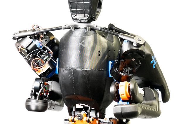
The Degrees Of Freedom (DOF) in the robot's extremities helps it to be flexible to perform various day to day tasks that a human can do. Most robots have a rigid/minimum DOF upper body which limits it to perform activities such as getting up from the ground, leaning over to pick up things from the ground, etc. For a robot to be capable of doing such tasks high DOF in the upper body along with higher Range of Motion (ROM) is required. So my second topic focuses on researching designs to optimize for higher DOF and ROM on the upper body while minimizing the swept volume of the actuators. Nadia currently has a planetary Yaw actuator in the pelvis and couple of linear hydraulic actuators which are coupled through a differential joint to perform Torso Pitch and Roll.
The goal of the project was to design a new 3 DOF Torso that is lightweight, capable of having Onboard Hydraulic Power Unit (HPU), Computing/Electronics and Battery. The other important goal that we pursued during this sprint is to design joints that have zero/minimum Backlash. At the Yaw Axis, the prebuilt cycloid actuators that were designed for the new shoulder joint of the robot were chosen because they matched the required torque and speed profile along with the zero backlash requirement. One drawback of the design was the loading condition on the robot. The Torso experiences huge moment loading (300Nm) condition compared to the shoulder. So moment loading testing on the actuator was carried out along with FEA on all the parts. The results showed that the actuator designed was not capable of meeting the loading conditions.
To reduce backlash and swept volume, I started looking into push push actuator setup and optimization. The ability to have pressure on both sides of the joint allows the actuator to move through the ROM without having to worry about backlash. This also allows the robot to have similar torque profiles while extension and retraction stroke of the cylinder which is beneficial compared to a regular hydraulic actuator. Different linkage kinematics were studied, but a bar kinematics was chosen because of its simplicity and its potential to achieve a lightweight system. An optimization algorithm minimized the swept volume of the mechanism and the results such as optimized mounting locations, actuator force and crank arm length were imported to CAD for design.

Custom Hydraulic Actuator Assembly and Pressure Test

Nadia is a hybrid system where certain joints that require high torque capability uses hydraulic actuators and others use electric actuators. As a next big step in the development process we decided to build custom hydraulic actuators to control the robot's overall weight and design actuators based on the joint requirements. The valves required to control hydraulic actuators have very small orifices. So the system has to be clean of any impurities. To do so, the manufactured parts were set in an ultrasonic cleaner to remove debris from manufacturing and were wiped down with lint free paper towels.
The system used both static and dynamic seals for their moving and stationary parts. The assembly process involved piston (plunger and rod), manifold, cylinder rear and front (rod seal puck) assembly which required careful attention to prevent seal damage.
After assembly the procedure was carefully documented and moved to another cleaning process using the hydraulic pump. This procedure removed any other impurities that are present inside the cylinder. So the hose from the pump was set to a lower pressure and the cylinder was cleaned overnight.
For the final test we increased the pressure in small steps from 100 to 3000psi to observe leaks in the assembled cylinder. Once we observed no leaks in the system at the highest pressure we started cycling the cylinder back and forth to observe cylinder movement.
As next steps we are planning to characterize the system to observe static and dynamic friction and identify possible other seal manufacturers and designs for different joint requirements.
SKILLS LEARNED FROM THE PROJECT
Wire Molding and Strain Relieving for High Force Application and Water Resistance
Hydraulic Actuator Design, Assembly, Inspection and Cleaning Process
Optimization of Linkage Design and Kinematics for form fitting
Compliant System Design for Manufacturing
Compliant Systems Load Testing and Characterization
Actuator Load Testing to Identify Part Stiffness and Bearing Specifications
Bearing Vision for Exoskeletons
Multi Degree of Freedom Hip Joint requirements for Exoskeleton
Onshape Software - Robot Kinematic Skeleton, Parameterized Design
Solidworks - FEA, Fatigue Cycle Testing and Compliance FEA model requirements
Python for Kinematics and Actuator Characterization
Actuator Design for Robotic System
Biped Design, Controls and Architecture
Electrical Debugging
GD&T drawing and Tolerances

