Vishnu Aishwaryan Subra Mani
EVA
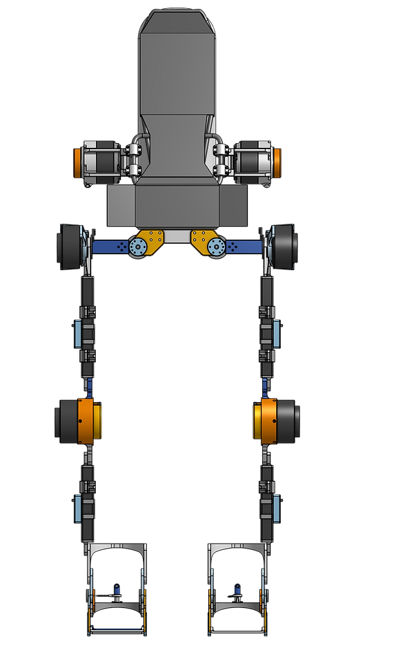
IHMC is developing an augmentative exoskeleton named EVA to offload backpack weight to assist Department of Energy Workers. As part of the team, I have been exploring ways to design hip joints for the exoskeleton to allow the user to have natural range of motion while providing assistance along the sagittal plane. We follow an iterative design approach to explore ideas which we test to see if it meets our requirement. We created a first prototype to act as a test platform on which we could explore designs to test range of motions and control approaches to test torque transferring capabilities.
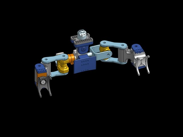
Mark 0 - 3 Degree of Freedom Hip Joint

The vision for Mark 0 was to conceptualize a design, 3D print them to actual form factor and actively test its performance. The goals for the design was to maximize user's Range of Motion while assisting them along the Sagittal Plane. Keeping the goal in mind I designed a hip joint to have 3 Degrees of Freedom
Pitch - Flexion/Extension
Roll - Abduction/Adduction
Yaw - Internal/External Rotation
The yaw joint was designed as a serial linkage system which transferred load along the sagittal plane while assisting the user to move comfortably along all the planes.
The roll joint was designed to be a passive pin joint collocated with the human joint for maximum Range of Motion along Frontal Plane which was planned to be swapped for a motor in the future for active control. During load testing the joint was constrained using locating pins to transfer backpack loads to the ground.
The pitch joint was actively controlled using a AK 10-9 Cubemars actuator. The torque requirements from calculation and fast iteration plan promoted the use of this off-the-shelf system.
DRAWBACKS: For a first prototype this system turned out to be challenging to design controllers due to the unconstrained and unsensored serial yaw joint. Due to limited soft good architecture and position based control trajectories the linkages moved a lot during walking.

Mark 1 - 2 Degree of Freedom Hip Joint
The aforementioned drawback led us to simplify the design of the hip joint into a 2 Degree of Freedom system which was designed for manufacturing. This led us to build a reliable. robust platform on which we could develop our control architecture. The design used an AK10-9 actuator along the pitch joint and a passive roll joint which was integrated into an off-the-shelf SCBA harness.
This set up was sufficient to design and test squat, gravity compensation, walking and other controllers.
During this design iteration other actuation systems such as belt drive and cycloid were explored to improve the torque assistance of the system to explore activities such as pushing and pulling a weighted cart.
DRAWBACKS: Mark 1 design made it hard for users to squat and to do short turn maneuvers. So it was hard to pick up objects from ground and limited the user's comfort and movements significantly.

Mark 1.5 - 3 Degree of Freedom Compliant Hip Joint
So to improve upon the drawbacks, I started tracking the problem and user inputs while testing which helped me identify that the system was too stiff along the yaw axis for users to squat. This helped me explore new approaches of making the design compliant while allowing load bearing capabilities along the sagittal plane.
The key to achieving such a system is based on design and identifying the optimum stiffness along gravity axis and compliance along yaw axis. I designed multiple iterations and 3d printed the structure with Markforged reinforced Carbon Fiber Inlay. I load tested these designs to characterize stiffness. This process was tedious and challenging but I was able to finalize a design with a particular 3d printing orientation to maximize the pitch axis stiffness while maximizing yaw axis compliance for load bearing exoskeletons.
DRAWBACKS: The proposed design is reliable and can withstand loads for a large cycles of operation with out failure. But to have a deployable solution which is safe the design has to be made robust and this can be achieved by switching from 3d printing to Composite (Carbon fiber) manufacturing. The other drawback that we noticed was the compliance along Yaw axis has to be optimized per person because each person's comfort level was different. These changes will be carried out in the next iteration of the device.
Mark 2.0 - High Torque Low Profile Cycloidal Drive

The rated torque of the AK10-9 was limited to 20Nm and the peak speed was 40rad/s. The size and dimensions of the actuator has hindered arm swing movement and most of this came because the motor driver was collocated with the actuator. As our controls and design got better, the estimated weight and load carrying capability of the device starting growing along with our goal for the project. We started exploring other maneuvers such as lifting, pushing and pulling a loaded cart for the work environment and other possible dynamic activities. To do so, the actuators had to be more powerful and lightweight. The high speed performance of AK10-9 actuators were not required for our applciation. Literature shows us that the max speed of 12 - 15 rad/s is adequate for dynamic exoskeleton. This motivated me to start exploring design concepts for a new actuator and a cycloidal drive seemed to be the optimum solution because of its small form factor and higher transmission ratio and still be optimum for open loop torque control. So I worked with my team to come up with a design where the cycloid reducers can be packaged inside an outrunner motor. The goal was to keep the actuator backdrivable and do an open loop torque control similar to the onboard Quasi-Direct Drive Actuator.

DRAWBACKS: Complicated design with more components but is capable of meeting our requirements. This design has been developed and is currently being tested and characterized.
SKILLS LEARNED FROM THE PROJECT
Linkage Design and Kinematics
Load Bearing Vision for Exoskeletons
Multi Degree of Freedom Hip Joint requirements for Exoskeleton
Compliant System Design for Manufacturing
Urethane Rubber Molding for Pressure Sensitive Sensors
Onshape Software - Robot Kinematic Skeleton, Parameterized Design
Solidworks - FEA, Fatigue Cycle Testing and Compliance FEA model requirements
Python for Kinematics and Actuator Characterization
Composite 3D Printing and Layer Orientation for maximum performance
Actuator Design for Robotic System
Human Subject Testing
Exoskeleton Control and Architecture
Electrical Debugging
GD&T drawing and Tolerances
Softgood Design